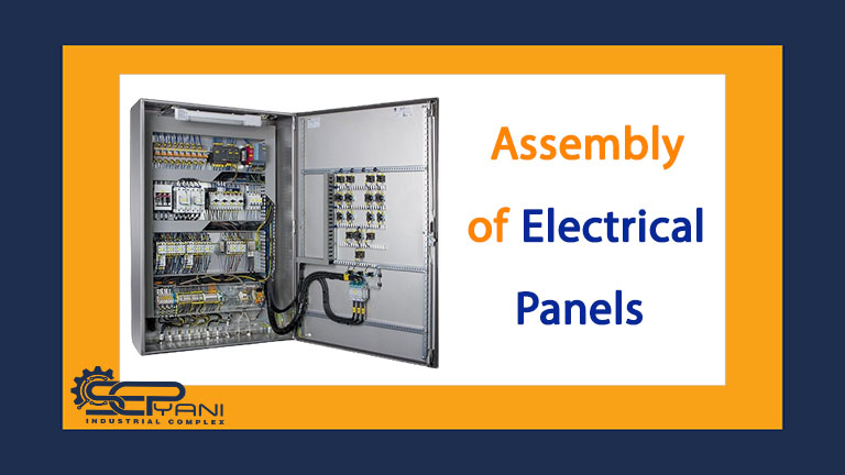
Electrical panel design and assembly
Electrical panels are essential components of any electrical system. They protect against overloads and short circuits, distribute power to different parts of the system, and allow for easy maintenance and troubleshooting. However, designing and assembling the electrical panel is a complex task that requires careful planning and attention to detail. In today’s article, Sepiani examines the process of designing and assembling electrical panels and starts with an introduction to electrical panels and their application.
Maintenance of Dairy Production Lines
Introduction of electrical panels
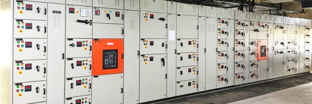
A switchboard is a set of electrical components that control the flow of electricity in an electrical system. It is basically a cabinet that houses electrical equipment such as fuses, circuit breakers, relays, transformers, etc. The switchboard acts as a central point for distributing power from a generator or power source to various loads in the system.
The switchboard is usually divided into compartments, each of which contains specific types of equipment. For example, there may be one compartment for high voltage equipment and another for low voltage equipment. The chambers are separated by barriers to prevent arcing between them.
Understanding the purpose of electrical panels
The main purpose of the switchboard is to protect electrical equipment and personnel from the harmful effects of electrical faults such as short circuit and overload. It does this by isolating faulty equipment and cutting off current to prevent damage and failure.
1. Electricity distribution
Another important task of electrical panels is the distribution of electricity in different parts of the electrical system. A switchboard receives power from a generator or power source and distributes it to loads such as motors, lighting systems, and other equipment.
2. Overload protection
Switchboards also provide overload protection. Overload occurs when the current passing through the circuit exceeds its rated capacity. This can lead to overheating and damage to the equipment, as well as a fire hazard. The panel has protective devices such as fuses and circuit breakers that detect and disconnect overloads to prevent damage.
3. Coordination of protective equipment
It is important to ensure that the protective devices in an electrical system are coordinated with each other for effective operation. This means that the device closest to the fault must be shut down first to isolate the fault and prevent damage. Switchboards play an important role in coordinating protective devices throughout the system.
4. Repair and troubleshooting
Another important task of electrical panels is to facilitate the maintenance and troubleshooting of the electrical system. The switchboard provides access to electrical equipment for inspection, testing, and repair. It also allows easy isolation of faulty equipment and identification of the source of electrical problems.
Electrical panel components and their functions
Switchboards are an essential part of any electrical system because they provide overload and short-circuit protection, distribute power to different parts of the system, and allow for easy maintenance and troubleshooting. In this article, we will examine in detail some components of electrical panels and their functions, as well as types of electrical panels.
Basbar
Busbar is one of the main components of electrical panel. Busbars are metal rods that conduct electric current between different components of the panel. These parts are usually made of copper or aluminum and are mounted on insulating material to prevent arcing. They are used to connect protective devices, distribution boards and control equipment to the power supply.
circuit breaker
Circuit breakers are another important component of the electrical panel. They protect electrical equipment and personnel from the harmful effects of overloads and short circuits. When an overload is detected, the circuit breaker trips and interrupts the current flow, preventing damage to the equipment.
fuses
Fuses are similar to circuit breakers in that they protect against overload and short circuit. However, unlike circuit breakers, fuses must be replaced after they are tripped. Fuses consist of a metal wire that melts when exposed to excessive current, breaking the circuit and protecting the equipment.
Distribution boards
Distribution boards are used to distribute electricity in different parts of the electrical system. They are usually mounted on DIN rails and connected to busbars using cables. Distribution boards may contain additional protective devices such as fuses or circuit breakers to further protect the equipment.
Control equipment
To control the operation of the electrical system, control equipment such as contactors and relays are used. Contactors are used to switch high voltage loads on and off, while relays are used to control low voltage circuits. They are usually mounted on DIN rails and connected to busbars using cables.
Transformers
Transformers are used to change the voltage level of the power source. They consist of two coils, one with more turns than the other. When AC current passes through a coil with more turns, it induces a current in the coil with fewer turns, resulting in a change in voltage. Depending on the needs of the electrical system, transformers may be used to increase or decrease the voltage.
Types of electrical panels
Low voltage panels
Low pressure panels are used in applications where the voltage level is less than 600 volts. They are usually used in commercial and residential buildings as well as in small manufacturing facilities. Low voltage switchboards usually contain protective devices such as circuit breakers and fuses, as well as distribution boards to distribute power to different parts of the system.
Medium voltage switchboard
Medium pressure switchboards are used in applications where the voltage level is between 600 and 35000 volts. They are commonly used in industrial facilities, large commercial buildings and substations. Medium voltage switchboards may have protective devices such as vacuum circuit breakers as well as transformers to change the voltage level of the power source.
High pressure switchboard
High voltage switchboard is used in applications where the voltage level is more than 35000 volts. They are usually used in substations and power plants. High voltage switchboards usually contain protective devices such as gas-insulated circuit breakers as well as transformers to change the voltage level of the power supply.
Key considerations in electrical panel design
When designing a switchboard, there are several key points to consider. These include load requirements, board size, layout, material selection, and required protective equipment.
Loading requirements
The first point in the design of the electrical panel is the required load of the system. This includes determining the amount of power required to run the various loads in the system as well as the current rating of each load. The panel must be designed to withstand the maximum expected load without exceeding its rated capacity. Failure to properly design for load requirements can lead to overloading and equipment failure.
The size of the electrical panel
Once the load requirements are determined, the next consideration is board size. The size of the panel depends on the number and type of system loads, as well as the available space for installation. A larger switchboard may be required if the system has a large number of loads or if it requires additional enclosures for specific equipment.
Layout
The layout of the electrical panel is another important point in the design of the electrical panel. This location of enclosures, distribution boards, and other components must be carefully planned to ensure efficient operation and ease of maintenance. So layout should consider the need for free space around the equipment for easy access and adequate ventilation to prevent overheating.
Material selection
The materials used in the construction of electrical panels are also important. The board must be made of materials that are resistant to corrosion and damage from environmental factors such as moisture and dust. Common materials used include steel, aluminum, and fiberglass.
Protective equipment
Finally, the panel must be equipped with protective devices such as fuses, relays to protect against overload and short circuit. The selection of protection devices should be based on the load requirement, voltage level and the type of protected equipment.
What are CNC Milling and Turning?
How to assemble the electrical panel
After designing the electrical panel, the next step is its assembly. Assembling an electrical panel is a complex process that requires expertise in electrical wiring and knowledge of safety procedures. Following are the steps related to assembling the electrical panel:
Prepare the electrical panel box.
The first stage is the preparation of the panel housing. This includes cleaning the housing, removing any holes or sharp edges, and drilling the parts to be installed.
Install the busbars.
In the next step, the busbars are installed. Busbars are copper or aluminum rods that conduct electrical current between different components of the panel. They are installed using screws and secured to the housing.
Install circuit breakers and other protective devices.
After installing busbars and other protective devices are installed. These devices are mounted on DIN rails that are attached to the enclosure. Then the protective devices are connected to the busbars using cables.
Install distribution boards.
The distribution boards are installed in the next step. These panels are used to distribute electricity in different parts of the system. They are usually mounted on DIN rails and connected to busbars using cables.
Install control equipment.
Control equipment such as contactors and relays are installed in the next step. These devices are used to control the operation of the electrical system. They are mounted on DIN rails and connected to busbars using cables.
Wire the parts.
After installing all the components, the next step is to wire them together. This step includes connecting cables from protective devices, distribution boards and control equipment to the busbars. Wires are connected using crimp terminals or screw terminals.
Test the system.
After the parts are connected together, the system is tested to make sure it works properly. This test includes checking voltage levels, testing protective devices, and making sure the system is properly grounded.
Testing and setting up a switchboard
Once the switchboard is designed and assembled, it must be tested and commissioned to ensure proper operation. Testing and commissioning includes checking the performance of each component, checking the correct operation of all protective devices and ensuring the correct connection of the electrical panel. In this section of the article, the steps related to testing and setting up the electrical panel are given:
visual inspection
The first step in testing and commissioning the switchboard is to perform a visual inspection. This includes checking for loose connections, damaged parts or wiring and making sure all parts are installed correctly.
Functional testing
Functional test includes checking the performance of each part in the board. This includes testing circuit , fuses, switchboards, control equipment and transformers to ensure they are working properly.
Safety device test
Protective device testing includes checking the performance of protective devices such as relays. This includes testing the trip settings to ensure they function properly and calibrating them to provide the appropriate level of protection.
Ground test
A ground test involves verifying that the electrical panel is properly grounded to protect against electric shock and other safety hazards. This step may include using a ground tester to measure the resistance between the board and ground.
Insulation resistance test
The insulation resistance test consists of measuring the insulation resistance of the board to check the absence of short circuit or other faults in the insulation. This may involve using a megohm meter to measure the resistance between various components in the electrical panel.
Load bank test
A load bank test involves simulating the load on the panel to ensure that it can withstand the maximum expected load. This may involve connecting the load bank to the switchboard and gradually increasing the load while monitoring the operation of the protective devices.
Conclusion
The design and assembly of the electrical panel requires careful planning and attention to detail. When designing the switchboard, it is very important to pay attention to the load requirements, the size of the switchboard, the layout, the choice of materials and the required protection devices. Assembling an electrical panel requires expertise in electrical wiring and knowledge of safety procedures. By following the steps outlined in this article, you can ensure that your switchboard is designed and assembled to meet the needs of your electrical system.
After reading this article, if you have any questions or doubts regarding the design and assembly of electrical panels, you can get help from Sepiani experts free of charge. For more information, contact us now via WhatsApp.