What is an Encoder?
In simple words, an encoder is a measurement device that has feedback and is also referred to as an encoder. Basically encoders convert movement into an electrical signal. In other words, they can be read by some types of control devices in a control system such as a counter or PLC. This device sends a feedback signal that can be used to determine position, count, speed or direction.
What is Industrial Automation?
What is an Incremental Encoder?
It is a type of encoder equipment that converts the angular movement or shaft position to analog or digital code to identify the position or movement. These types of devices are one of the most widely used rotary encoders. An incremental encoder can be used in position feedback and motor speed applications that include servo/light, industrial or heavy duty applications. This model of encoders provide very good feedback for speed and distance.
How does it work?
An incremental encoder provides a certain number of pulses in one revolution. The output can be a single pulse line (one “A” channel) or two pulse lines (one “A” and “B” channel) adjusted to determine rotation. This phasing between two signals is called quadrature.
An incremental optical encoder consists of a rotary axis assembly, PCB and cover. The PCB contains an optical sensor that generates only two main signals for position and speed. For an incremental optical encoder, an optical sensor detects light as it passes through a marked disc. The disc moves as the plate assembly rotates and the information is converted into pulses by the PCB. For an incremental magnetic encoder, the optical sensor is replaced by a magnetic sensor and the rotating disc contains a series of magnetic poles.
Encoder index channel (Z):
An indicator or “Z” channel can be provided as a signal per revolution of one pulse to confirm the home and pulse count on the A and/or B channels. This indicator can be used for A or B in their different states. Commutation channels (U, V, W) can also be provided in some encoders. These signals are coordinated with the commutation coils in the servo motors. They also ensure that the drive or amplifier for those motors applies current to each coil in the correct order and at the correct level.
The difference between Incremental Encoders and Resolvers:
Resolvers are electromechanical encoders based on World War II technology. An electric current creates a magnetic field along a central coil. There are two coils that are perpendicular to each other. One coil is fixed in place and the other coil moves as the object moves. Changes in the strength and location of the two interacting magnetic fields allow the resolver to determine the motion of the object.
The difference between Incremental and Absolute Encoders:
Absolute encoders work in situations where the accuracy of speed and position, its error tolerance is more important than the simplicity of the system. This device has the ability to “know where it is” according to its position and if the system is turned off. Also if the encoder is in moving position during shutdown, it will restart. This type of encoder processes the positioning information itself and does not need to rely on external electronics to provide a baseline for the encoder’s position.
Especially compared to incremental encoders and resolvers, an obvious strength of absolute encoders is how their positioning accuracy affects overall performance. So usually these encoders are for higher precision applications like CNC, medical and robotics.
Uses and applications of incremental encoder:
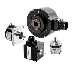
An incremental encoder is designed to be versatile and adjustable to suit a wide range of applications. Three general categories of its applications based on the environment are:
- Heavy duty: harsh environmental conditions with high probability of pollutants and humidity, high temperature, shock and vibration required as seen in pulp, paper, steel and wood factories.
- Industrial Application: Factory environment requiring standard IP rating, moderate shock, vibration and temperature characteristics as seen in food and beverage, textile, typically factory automation plants.
- Light duty: controlled environment with precision and high temperature such as robotics, electronics and semiconductors.
What is a quadrature encoder?
A quadrature encoder is an incremental encoder with 2 output channels (which are not in phase) used in many general automation applications where motion direction detection is required.
Each channel provides a certain number of equally spaced pulses per round (PPR) and the direction of movement is identified by the phase relationship of one channel leading or following the other.
How does a quadrature work?
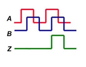
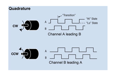
The code disk inside a square encoder consists of two tracks, usually representing channel A and channel B. These tracks or channels are electrically coded ninety degrees as shown in the image below and this is the key element of the design that provides the squaring. In applications where a direction sensor is required, a controller can determine the direction of motion based on the phase relationship between channels A and B.
As shown in the example optical encoder figure below. When the encoder is rotated clockwise, the signal indicates the leading channel B. Also, the opposite happens when the square encoder is rotated counterclockwise. Other than direction, position can be controlled with a square encoder by generating another signal called a “marker”, “index” or “Z channel”. This Z signal, generated once per full revolution of the square encoder, is often used to locate a specific position during a 360 degree rotation.
How and when to use square encoder?
Square encoders are used in two-way position measurement and length measurement applications. However, in some unidirectional start-stop applications, it is important to have bidirectional information (channel A and B) even if reverse shaft rotation is not anticipated.
A counting error may occur in the system with a single-channel encoder due to machine vibration. For example, a counting error may occur with a single-channel encoder in a start/stop application.
If the mechanical rotation stops while the output waveform is being transmitted. As the subsequent mechanical vibrations of the shaft drive the output back and forth on the edge, the counter increments with each transition, even if the system is almost stopped. Using a quadrature encoder, the transmission counter monitors its relationship to the state of the opposite channel and can generate reliable position information.
Achieving higher resolution with Quadrature Encoders:
When more resolution is needed, the counter can count the leading and trailing edges of the square encoder pulse train from a single channel, doubling the number of pulses per cycle. Counting the leading and trailing edges of both channels (channels A and B) of a square encoder quadruples the number of pulses per cycle.
This technique is known as encoder and depends on how the signal code is read by the user drive, PLC or controller. Consequently, 10000 pulses per turn can be generated from a 2500 PPR square encoder.
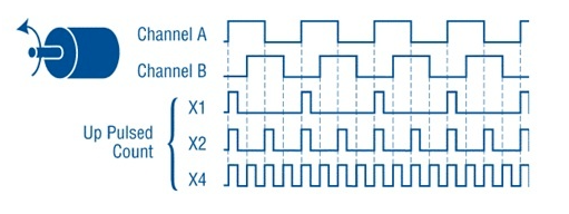
Typically with an encoder, this signal will be 4x to more than ±1 count accurate. Likewise, 40000 pulses can be generated from a 10000 PPR square encoder. By activating the high and low edges of the pulse train, we can double or quadruple the counts in each round of the same square encoder disc. This technique can be an effective way to increase the resolution without changing the disk code. However, it requires a well-functioning square wave output for effective detection.
Also care must be taken in choosing the output driver. Especially in long cables or in noisy environments. The accuracy of the quadrature encoder output must also be considered as this is also multiplied by the encoding factor.
How to choose a quadrature encoder?
A shaft encoder with a coupler can be used. The hollow shaft encoder is another option that passes the motor shaft through the encoder for more accuracy. If your motor is used in a polluted or dirty environment, the magnetic encoder provides the most reliable feedback.
What is an optical encoder?
An optical encoder is a type of rotary encoder that uses a sensor to detect a change in position as light passes through the encoder’s patterned wheel or disc.
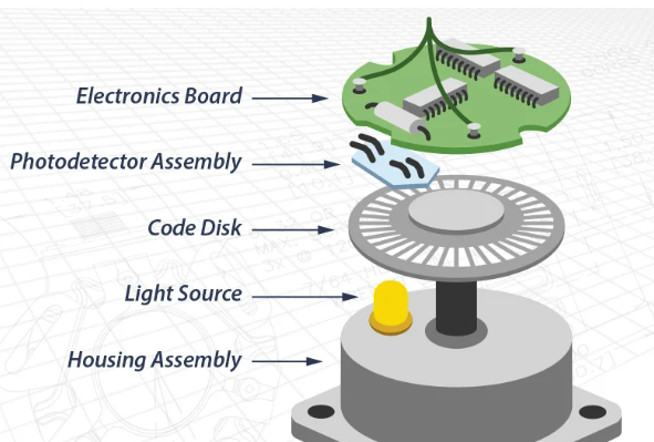
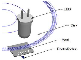
There are four components in an optical encoder:
- Light source (LED lamp)
- A sensor
- A moving disk
- A fixed mask
Different Types of Industrial Sensors
The way an optical encoder works:
The LED shines on the optical encoder shaft from one side. An encoder disc or disc has a series of tracks on it, similar to the concentric grooves on an LP. The mask has a corresponding track for each track on the optical encoder disk, and small holes called windows are created along the tracks in the mask.
As the disk moves, various apertures in the mask are closed or opened, indicating the movement and position of the optical shaft encoder. Each arc represents a different position in the rotation and has a different pattern of open/closed apertures. The sensor behind the mask detects the current pattern of optical encoders.
The role of encoder engine to determine information:
Each sensor represents a single signal to the optical encoder. A track can contain two sensors that are set to give two slightly different signals simultaneously. These offset signals can be used by the optical encoder motor to determine more precise motion information, such as speed. The second path can be used to give an indicator pulse once per round and provides a way to direct the signals.
Phased array optical rotary encoders:
More reliable than basic mask optical encoders are phased array optical rotary encoders. Optical encoders use multiple signal outputs to average together to create a single signal that is generated by the motor output.
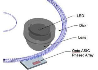
How phased array optical rotary-encoders work:
This multiple signal used by an optical shaft encoder is called an array. By using averages instead of a single reading, phased optical array encoders have much more stable signals. Therefore, they can be used in less stable environments such as mining or heavy production. Where vibration or shock can affect the traditional mask optical shaft encoder.
Magnetic motor technology:
- A magnetic encoder uses the same principle to determine the position of an optical shaft encoder, but it does so using magnetic fields instead of light.
- With a magnetic encoder, a large magnetic wheel rotates on a plate of magnetic resistance sensors. As the disc rotates on the mask to pass light in predictable patterns.
- The wheel also produces predictable responses in the sensor based on the strength of the magnetic field. The magnetic response is fed through an electrical signal conditioning circuit. The magnetic encoder as a signal generating device is not affected by very harsh environments such as dust, moisture, extreme temperatures and shock.
Conclusion:
Sepyani Industrial Group, consisting of experienced and expert engineers, is ready to provide industrial automation services. Among the main services of our group are consulting, maintenance and design and start-up of automation of production lines of all kinds of factories. In addition to industrial automation services, you can buy all kinds of industrial parts related to automation from our exclusive store. You can contact us for more information. Also you can contact us by What’sApp.